A Critical Component of the Alaskan Water Cycle and Climate Change
| Flux Monitoring Instruments |
Following is the schematic diagram and field photograph of the ET flux tower with flux monitoring instruments (Credits: Jordi Cristobal. This Project). To enlarge the schematic diagram click on it.
 |
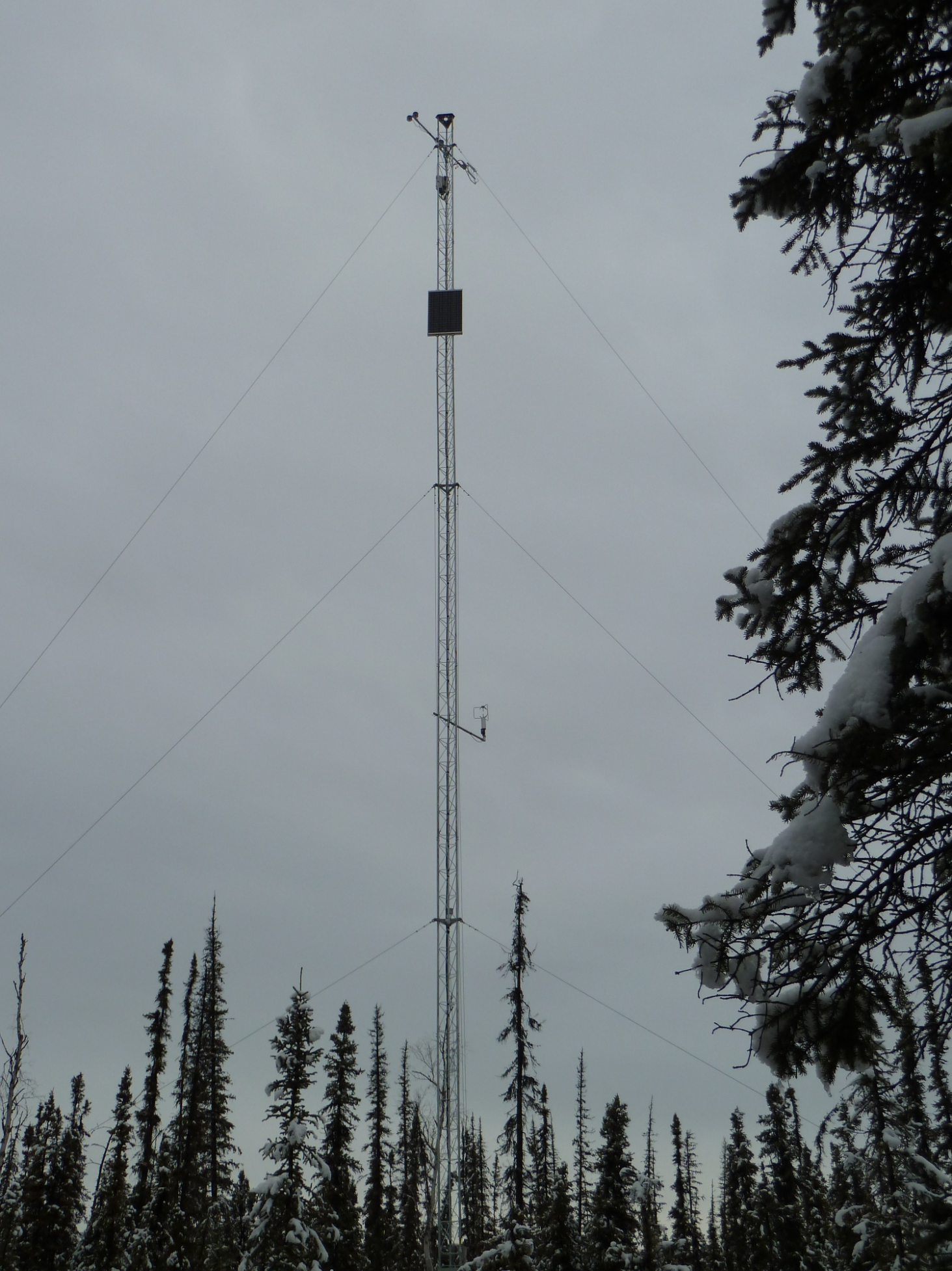 |
Tower instruments include:
- A. Hukseflux component net radiometer
- B. Campbell sonic anemometer
- C. RM Young sonic anemometer
- D. Campbell open path gas analyzer
- E. Air temperature sensors
- F. Eddy covariance processing unit
- G. Solar panel
- H. Data logger
- I. Vaisala barometric pressure sensors
| Ground Heat Monitoring Instruments |
The set-up for measuring ground heat parameters is schematically shown here.
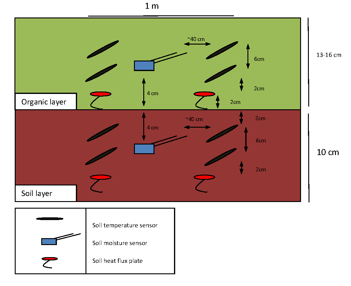
In this schematic blue boxes depict soil moisture sensors; red ovals depict heat flux plates; and black ovals depict the location of 8 temperature sensors. Credits: Jordi Cristobal. This Project.
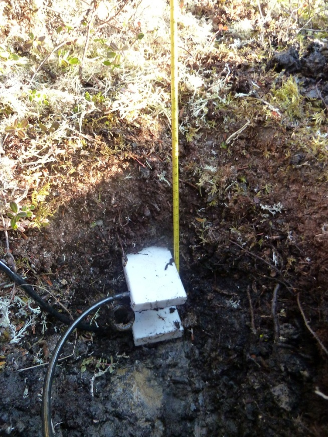
Field photos of the ground heat sensor installations are shown here:
 |
 |
| Scintillometers |
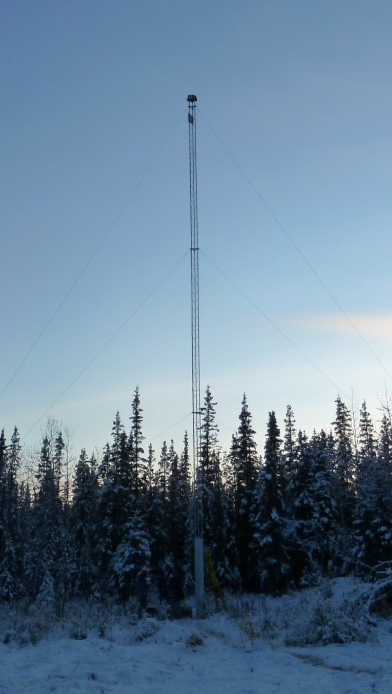
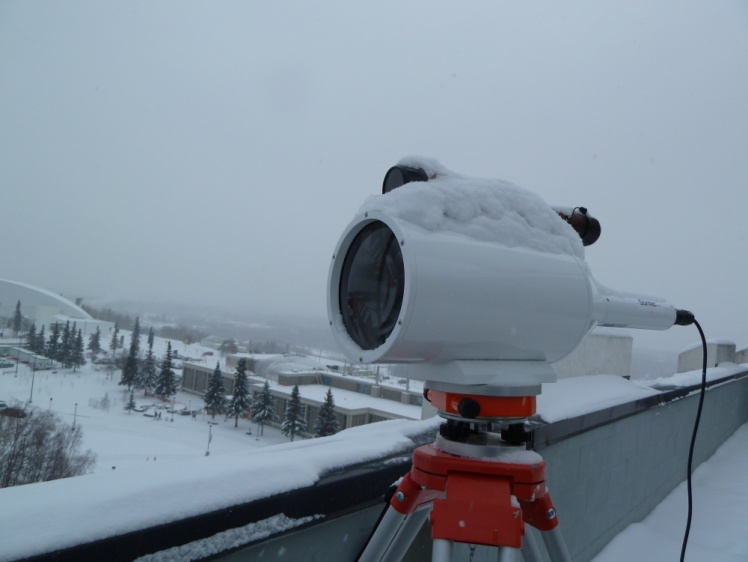
We installed the laser scintillometer transmitter unit on an 80 ft high tower, and installed the receiver unit on a tripod placed on the roof of the Geophysical Institute. Clockwise from the top left these photos show the general view of the scintillometer transmitter tower, the process of installing the scintillometer transmitter unit on the tower, and a close-up view of the laser scintillometer receiver unit, respectively.
 |
 |
 | |
